Los videos publicados por Tesla, junto con el video de desmontaje de MUNRO y la tecnología exhibida en la Gigafactory Austin de Tesla, han revelado más detalles sobre la tecnología de celdas 4680 y la tecnología CTC. Combinando esto con las revelaciones adicionales de la exhibición tecnológica de Tesla en Berlín, ahora podemos discernir un cierto marco con respecto a la disposición de las celdas 4680, el diseño y ensamblaje de los módulos, las placas de enfriamiento y el diseño general del PACK.
Como líder en vehículos eléctricos, el sistema de refrigeración líquida de la batería 4680 de Tesla y su diseño holístico PACK justifican un mayor debate.
1. Comparison of 4680 Cell Layout Designs

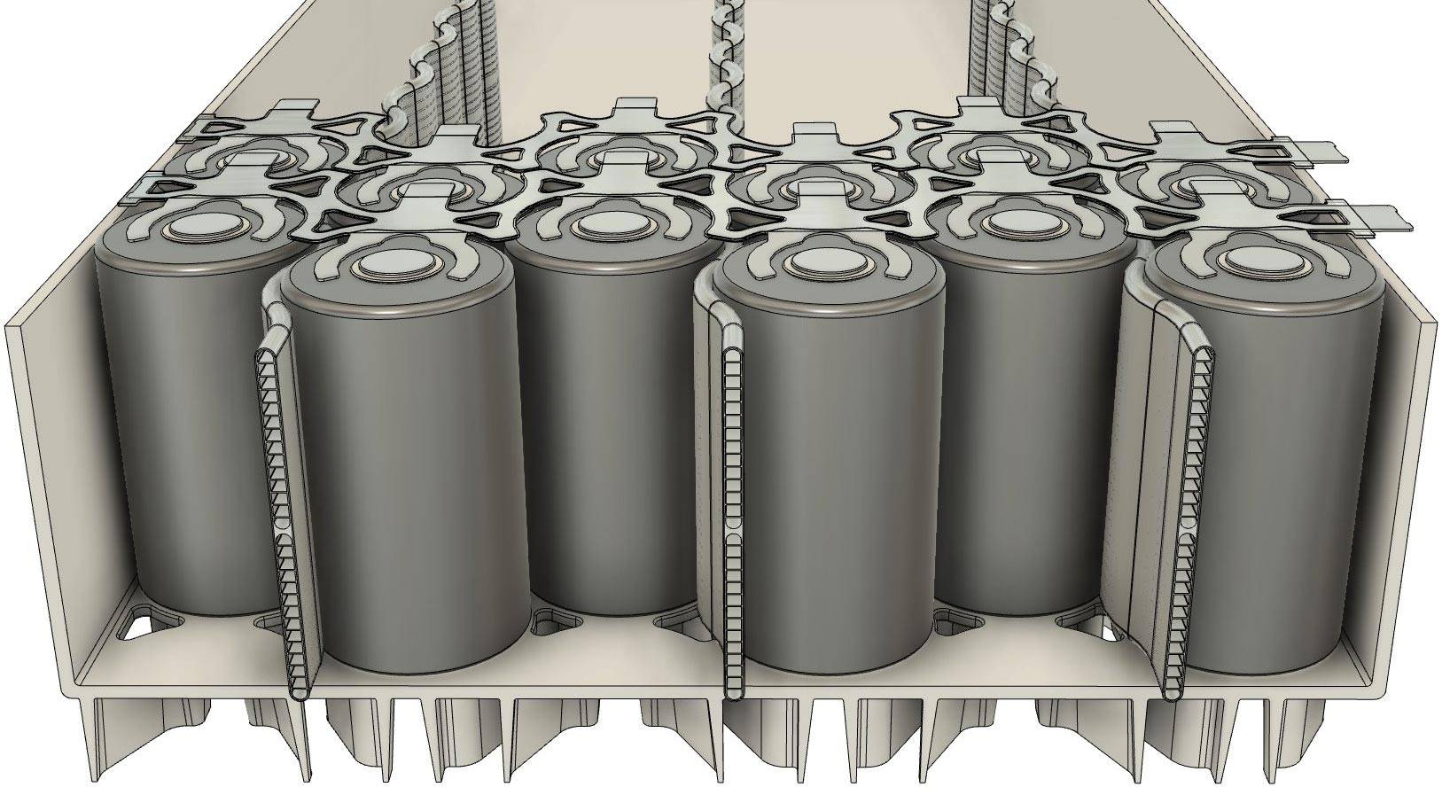
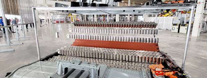
Comparatively, the layout scheme at Gigafactory Austin, Texas, resembles the current M3/Y’s large module arrangement. It consists of 4 elongated blocks, with each block containing 3 sets of cell columns. Each cell column comprises two cell rows and a water-cooling pipe, totaling 35 + 34 = 69 cells per set of columns. Thus, each block contains a total of 69 * 3 = 207 cells, resulting in a total of 828 cells for the MY version showcased in Austin.
On the other hand, Gigafactory Berlin’s layout for the 4680 cells is more akin to the current S/X Plaid model, utilizing a configuration of 5 horizontally placed large modules for similar spatial optimization.
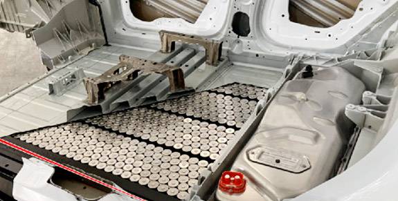
Layout of 4680 Cells at Gigafactory Austin
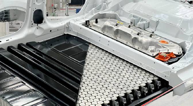
Layout of 4680 Cells at Gigafactory Berlin
The total number of cells in the Gigafactory Austin 4680 Pack
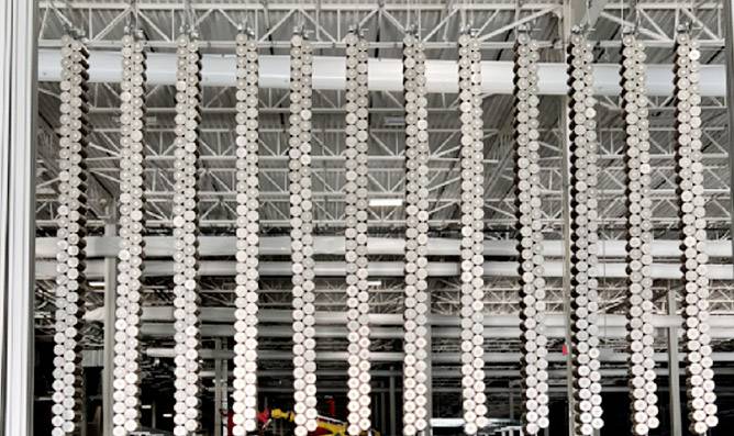
Bullet Belt Module
From the image above, as we count, each module consists of 35+34=69 cells, and with 3 such cell columns, that sums up to 207 cells. According to the latest MUNRO video, this translates to a configuration of 23 cells in series and 9 in parallel per module. With a total of 4 modules, the entire pack comprises 828 cells.
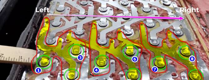
Parallel Aluminum Modules
From the 2170 version in the Model 3/Y to the S/X Plaid, and then to the 4680, Tesla gradually phased out the aluminum wire bonding approach. This shift was prompted by the increased current that the busbars needed to handle, posing challenges for thin aluminum wires. Instead, they adopted ‘aluminum tabs’ directly laser-welded to the positive and negative poles of the battery cells. This method allows for higher utilization of space in the Z-axis direction and simplifies the manufacturing process.
2. Comparison of 4680 Cell Layout Designs
The design still employs the earlier serpentine flat tube configuration.
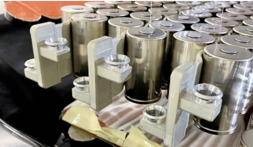
Terminal Bus Bars
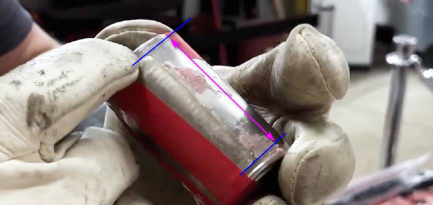
The Serpentine Tube Liquid Cooling System
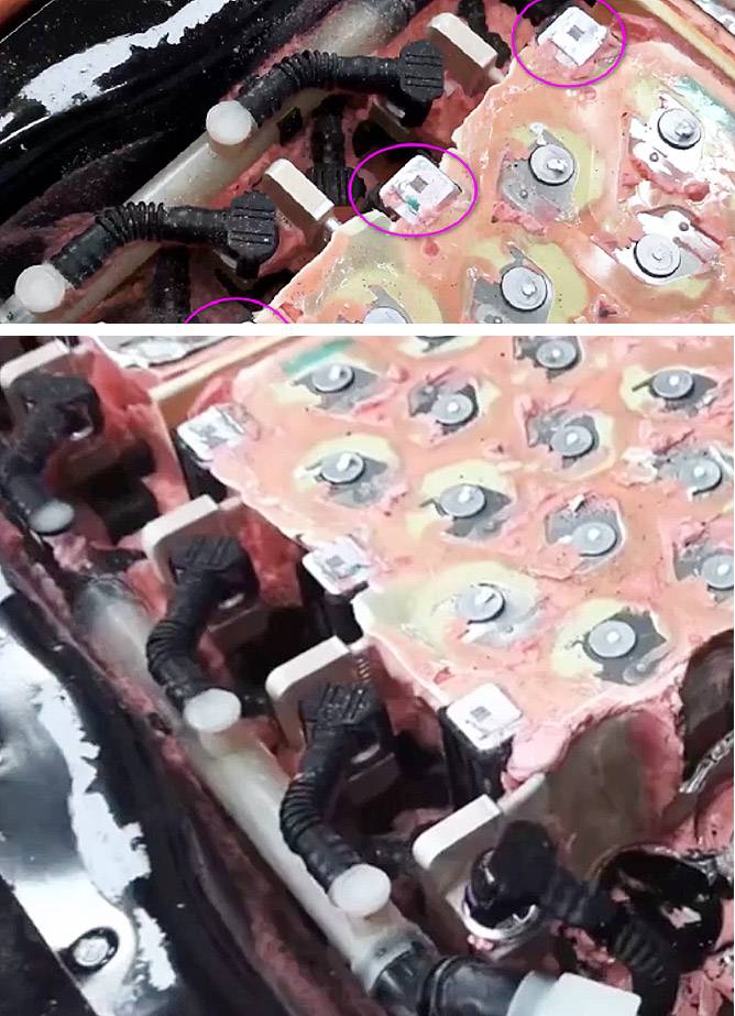
Disassembling the 4680 to Examine the Pipelines
We can see that the 4680 utilizes a dual main pipe configuration, employing a parallel multi-route approach for distribution, without introducing any significant new design elements.
Gigafactory Austin has confirmed the cooling design for this version of the 4680 pack, which is based on the dual-directional cooling tube design inherited from the S/X Plaid. Leveraging the vertical layout strategy, its inlet and outlet ports at the pack’s ends are similar to the current 3/Y models, as is the arrangement of the cooling pipelines. This configuration allows the BMS sampling section to be placed directly beneath the penthouse, saving routing and simplifying circuit connections.

Model 3 and Model Y use quick-connectors
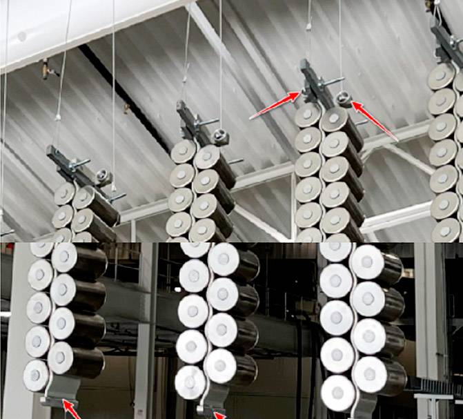
It utilizes U-shaped flow channel connectors, running in parallel, with terminal bus bars.
3. The design and assembly of module blocks
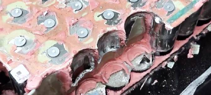
4680 Bracket Solution
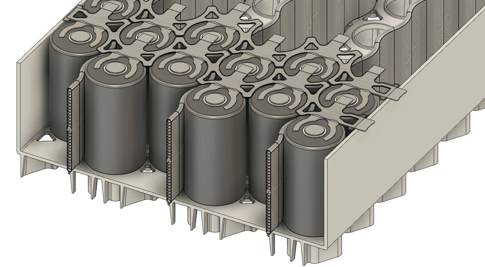
The bottom fixation of the cells is also quite evident; between the black bottom bracket and the cells, there are mica spacers installed. The cylindrical cells are conventionally arranged and supported by ABS brackets.
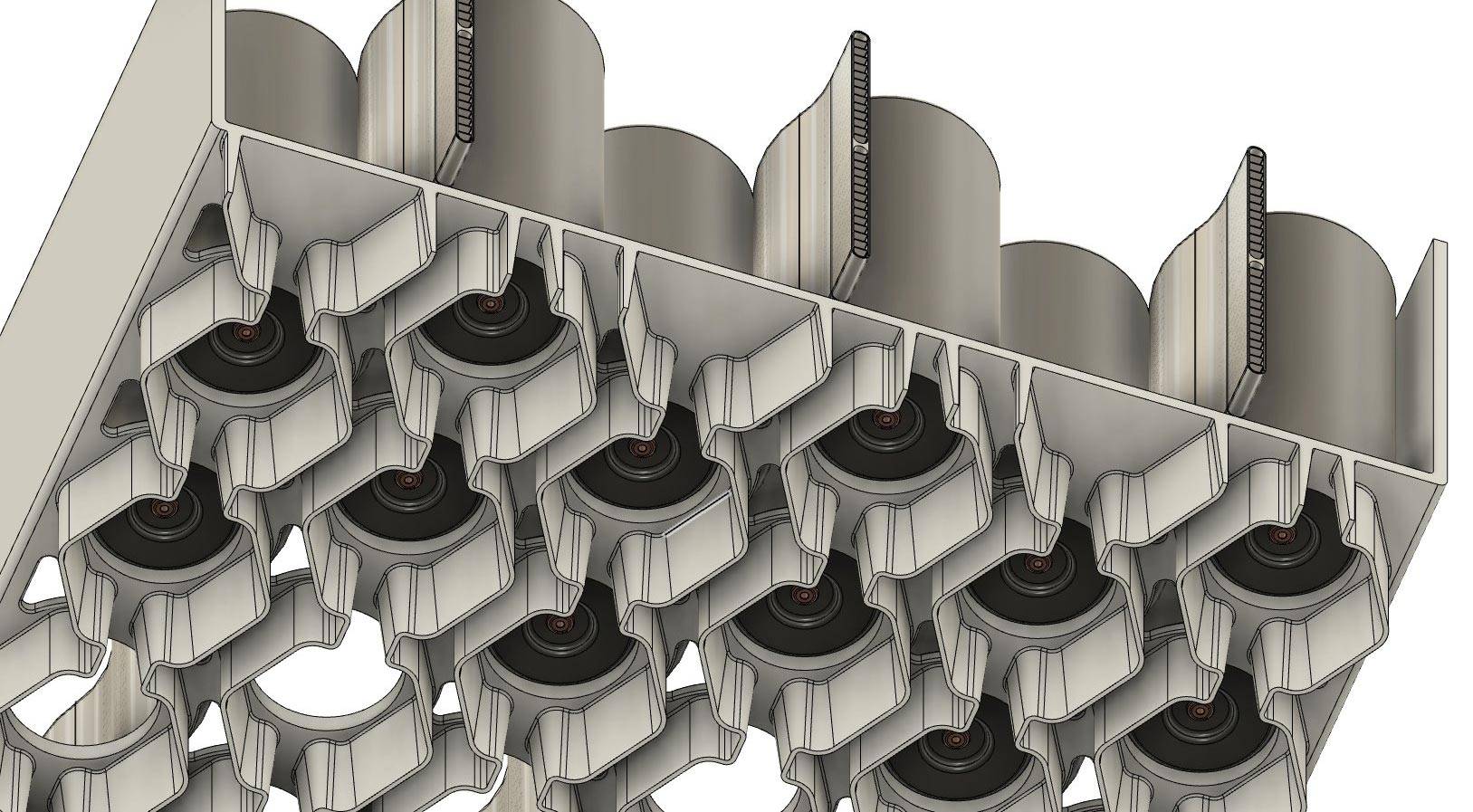
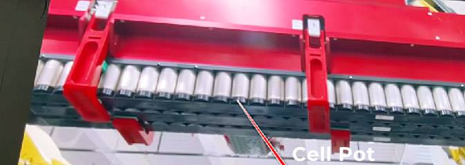
Each module block consists of three columns of cell groups. Once the cells are assembled with their respective cooling pipes, they are placed into corresponding pots and then the entire assembly is placed into the lower casing. When the cells release pressure downwards, the venting still occurs within the lower casing. The lower casing of the 4680 integrates a pathway for carrying the cells as well as providing a venting path for cell pressure release.
4. The arrangement of the entire pack
Let’s take another look at the overall pack layout; it’s similar to the S/X Plaid, with the high-voltage control integrated into the rear penthouse. Its fast-charging interface differs from the solution in Berlin as well.
The frontal view of the CTC pack
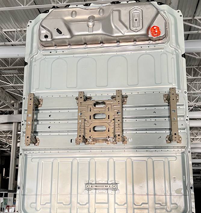
The outer casing of the entire pack
The integration of the CTC pack with the vehicle’s structure, from this perspective, shows that Gigafactory Austin’s layout of the 4680 cells has led to corresponding adjustments in its overall thermal runaway protection. The four orange components at the rear end of the lower casing seem to be balance valves (without integrated pressure relief), while it’s not evident on the sides of the casing whether they’ve incorporated pressure relief valves similar to those in Berlin’s 4680 setup.
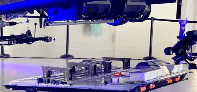
From these two demonstrations by Tesla of the 4680 plan, it appears there are at least two approaches being pursued internally, possibly for different high and low-end versions. Each approach is quite intriguing, as it both inherits previous technology and introduces further innovation. We eagerly anticipate its production plan.
5. MUNRO’s Physical Disassembly of the Entire Battery Pack
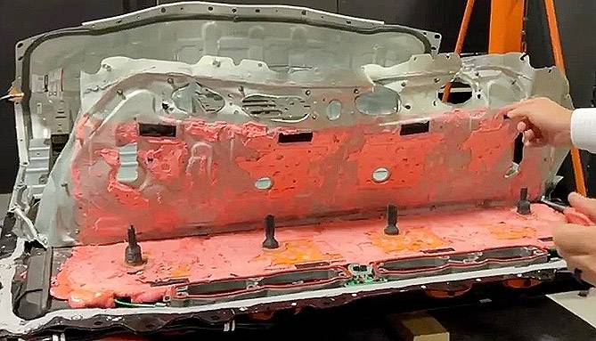
This is the latest release from the overseas disassembly firm Munro. Looking at this image, it’s clear that they’ve achieved the desired effect! Tesla incorporates the battery cells as an integral part of the entire battery and vehicle structure. Although Musk has mentioned using the cells to bear some shear forces and integrating the battery pack’s upper cover with the passenger cabin’s cover directly.
Essentially, they’ve employed an overall potting approach, where the adhesive primarily serves structural strength, bonding all components within the upper, lower, and shell (except for the Penthouse) together. Once the battery pack is assembled, it’s akin to a solid block of cement! Consequently, the entire pack, as a whole unit, exhibits exceptional mechanical performance. Stepping on it feels almost as sturdy as stepping on a floor.
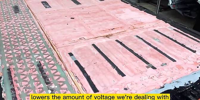
Here we can vaguely see the positions of the four “modules”. This older version of the Model Y still bears a strong resemblance. The significant difference lies in the fact that due to having the inlet and outlet pipes at the same end, the overall space occupied by the liquid cooling pipeline area is much larger than in the older version.
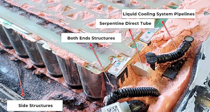
The overall internal liquid cooling framework
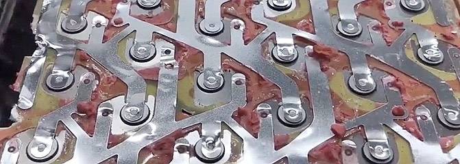
Series-Parallel Design
Another electrical change potentially more significant than the alterations on the busbars is the increased potential use of copper busbars compared to the previous Model Y; concerning the liquid cooling system, changes involve the layout of the coolant pipelines, their diameter, material, and other aspects.

Electrical Compartment Structure
This is the current adhesive fixation method we can observe within its main enclosure. Concerning the Penthouse (distribution box), there have been notable structural changes, an overall increase in height, and alterations in the sealing mechanism. In terms of electrical layout, the major spatial utilization hasn’t changed much, but specific components like the Pyrofuse have been repositioned. This is because accessing the distribution box cover from inside the vehicle is necessary to disconnect the high-voltage circuit, prioritizing safety during maintenance.
Furthermore, the fundamental framework for securing and sealing between the most crucial component, the battery pack, and the vehicle within the CTC, appears to be fairly clear:
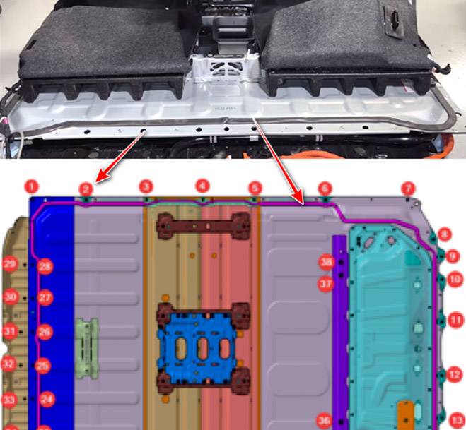
A ring of main sealing adhesive, along with 38 bolts, secures the entire battery pack, including the top cover and the floor, to the vehicle. At the system level, there is another noteworthy aspect: the battery pack has a bottom protective plate, which, when combined with the lower casing, provides structural support, completing the integration of the structural casing. This design is a common practice among various battery pack manufacturers.
6. PACK Design Logical Considerations
From the fixation of the entire battery cells and the high-voltage connections, Tesla’s CTC, in its specific integration, utilizes an adhesive bonding approach to transfer the force from the casing to the battery cells. The stress on these connecting components is relatively minimal.

Internal Module Structure
The fundamental basis for thermal runaway protection is similar between the current M3/Y and Tesla’s aim, which is to primarily control thermal runaway at the “module” level, reducing the overall explosion pressure at the casing level significantly.
Tesla has two evolving technological paths:
(1) Berlin’s 4680: Model S/X → S/X Plaid (CTP) → 4680 CTC
(2) Texas’s 4680: Model S/X → Model 3/Y Large Modules → 4680 CTC
Overall, several key design focuses are evident within the Tesla-4680PACK battery pack:
(1) Liquid cooling system design:
Adhering to the serpent-shaped tube-flat tube design, employing new adhesive techniques, and adopting a new module format (one serpent-shaped tube coupled with two battery cells to form a chain).
(2) Thermal runaway protection design:
Incorporating bottom VENT valve design, directly linked to the overall battery cell scheme.
(3) Lower casing design:
Consideration is required for VENT valve pathways and smoke channel design, with the battery cell’s explosion valves spraying downwards, involving a hollowed-out structure between the lower casing and the battery cells.
(4) Inter-cell electrical connection method:
Returning to the conventional aluminum foil welding method used with 18650 cells, adopting laser welding, presenting new challenges in welding technology and reliability.
(5) Configuration transition from CTP to CTC:
Observing Tesla’s alternate 4680 design without modules and the current Kirin 3.0’s side-cooling concept, it involves removing cross-beams from the casing, reinforcing the entire pack using auxiliary aluminum plates, potentially forming a pathway toward CTC.
